Inspiration
I designed this traffic light to replace an improvised device that I had build for my parents office in 2020. At the time the COVID social distancing restrictions were very strict and they had to extend the waiting room onto the stairwell to accomodate their waiting patients. For this they needed a way to call in patients one by one, and so I build a small WiFi-controlled device that would light up green to signal the next patient to come in. This worked great, but during is lifetime over the last 3 years, more and more LEDs on the device were starting to fail and each had to be manually replaced or removed by me. When it became clear that this waiting room system was working very well and that it was here to stay, I decided to build a new and improved version.
Overview
The main goals were simple. The device should look more like a real traffic light (so that patients could easily recognize at first sight what the red signal means) and its LEDs should be user-replaceable (so that I would not have to drive over to desolder broken LEDs). Of course, the setup should also be as simple and cheap as possible while remaining visually pleasing and reliable.
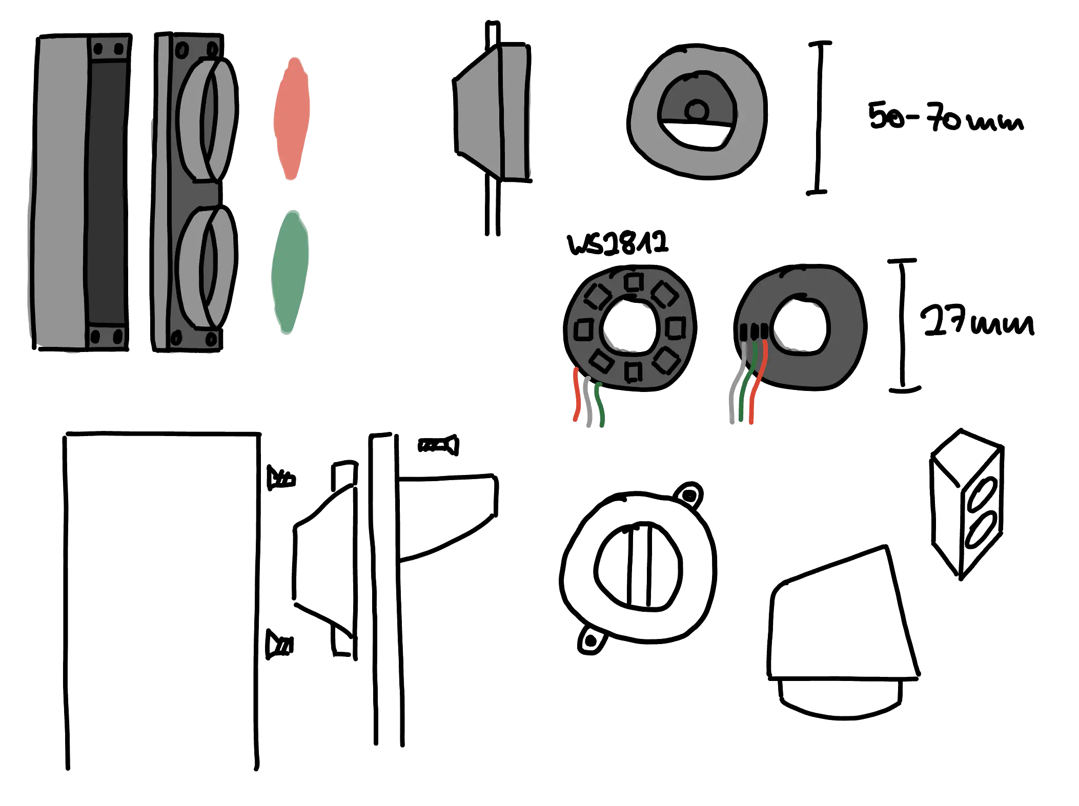
With these goals, fancy ideas such as soldering individual cob LEDs to a 3D structure of brass wire and encasing it in clear epoxy resin were off the table (even though I had already envisioned something like that and I am sure it would’ve looked great). Instead, I decided to go with a much simpler setup, using very similar components to the device I had designed before. The LEDs would still be WS2812s, but this time as two ring-shaped modules, and the NodeMCU would be replaced by a bare ESP-01. The main difference would be the design of the case.
Parts used:
- 2 WS2812 Rings (8 LEDs each) ~1.5€ ea.
- ESP-01 ~0.87€
- AMS1117 3.3V ~0.04€
- DC Barrel Jack and Plug ~0.15€
- 500 µF Capacitor
- 100 Ohm Resistor
- 24 AWG Wire
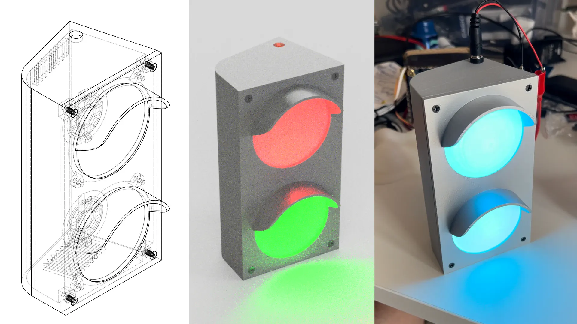
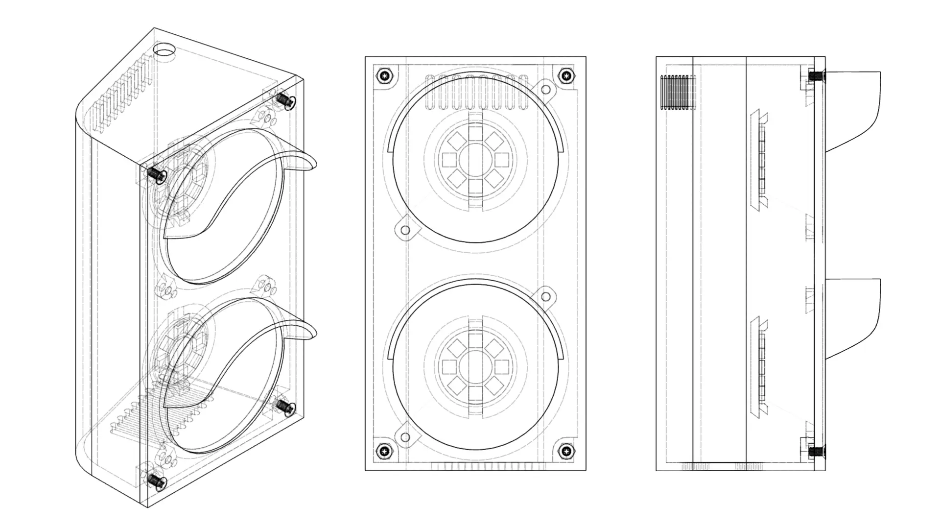
Design
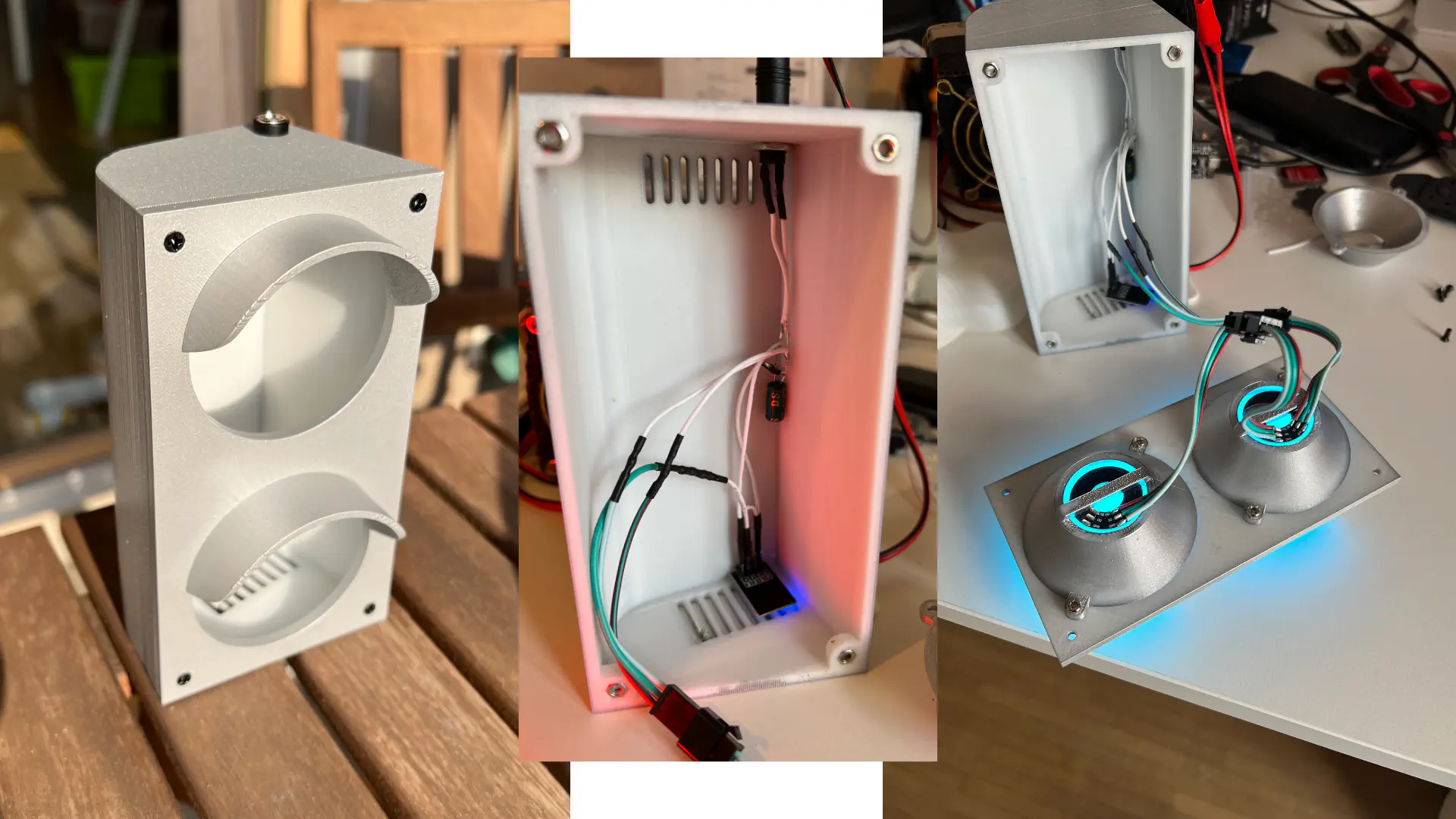
For the case, I took inspiration from real traffic lights and tried to include the essential design elements. Even though the device will not be used in direct sunlight, I added a small sun shade and tried to keep all other proportions somewhat realistic. I am quite happy with how the design turned out.
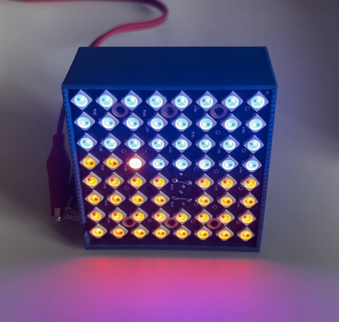
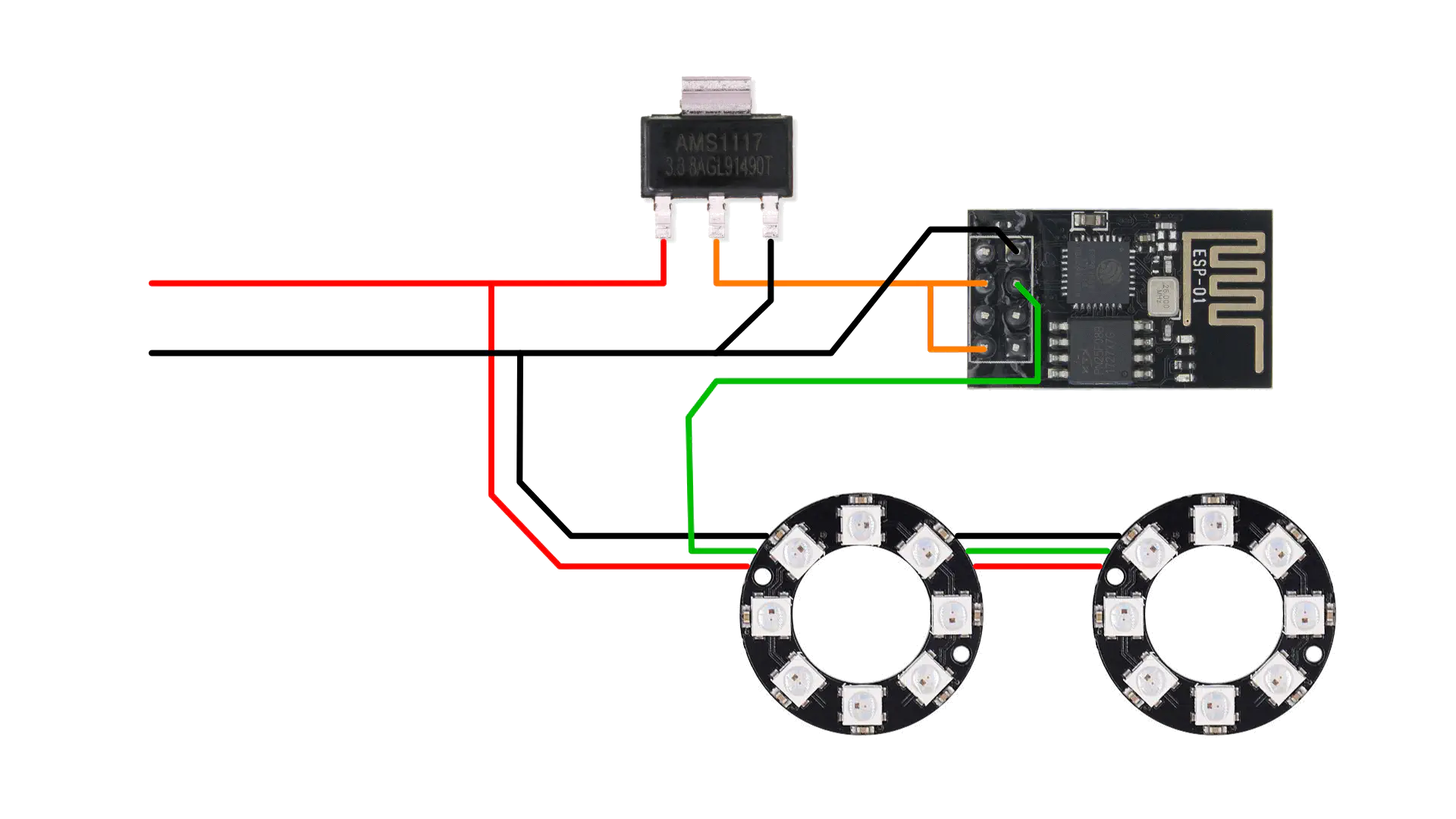
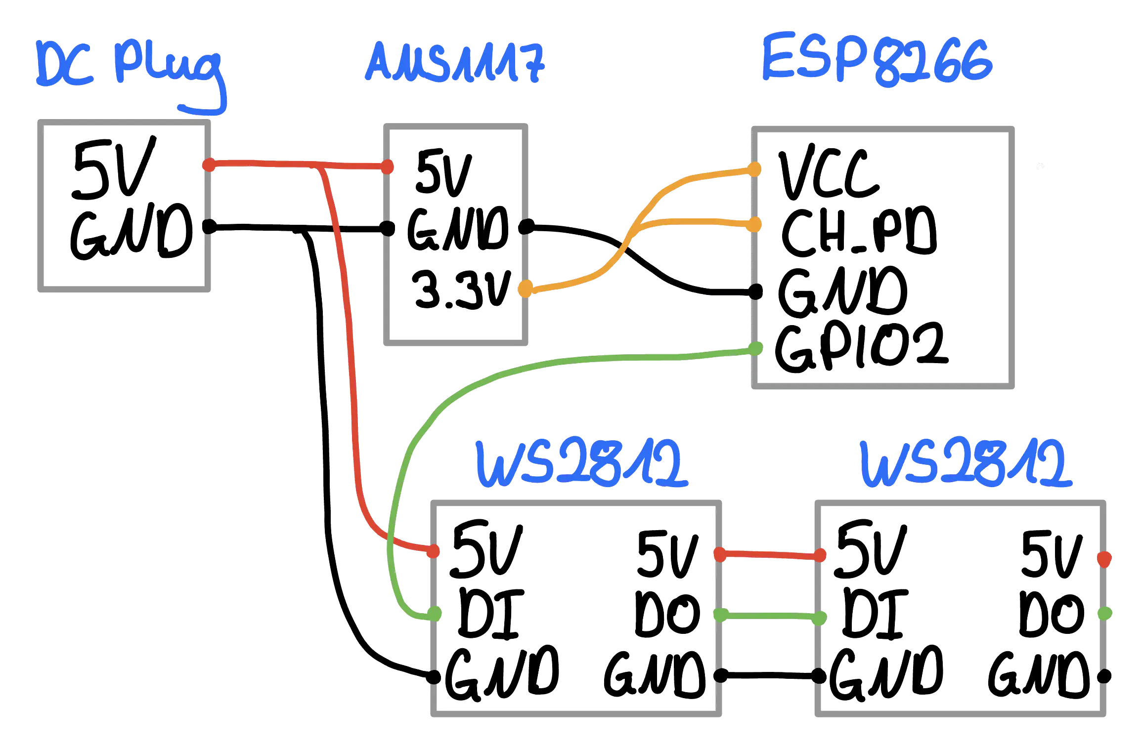
Wiring
While the case was printing on my 3D printer (15 hours for the largest part), I started testing the components and the indended wiring. For projects involving ESP-01s, I like to first test everything using a NodeMCU or similar dev-board so that debugging is easier and flashing can be done in place. Then, after writing some minimal code to test the LEDs and ensuring that the OTA update function worked, I flashed the firmware onto an ESP-01 and soldered everything together.
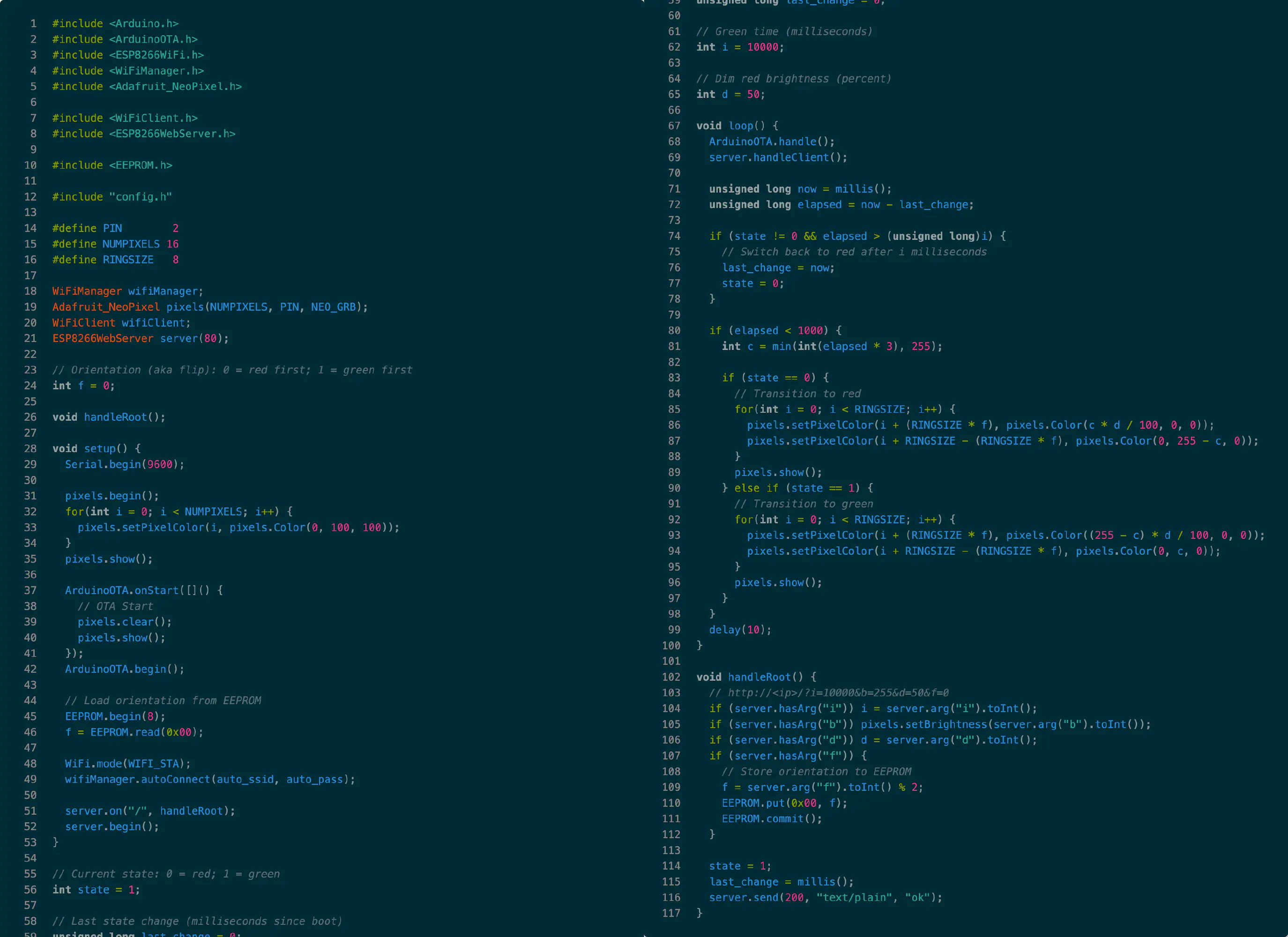
Code
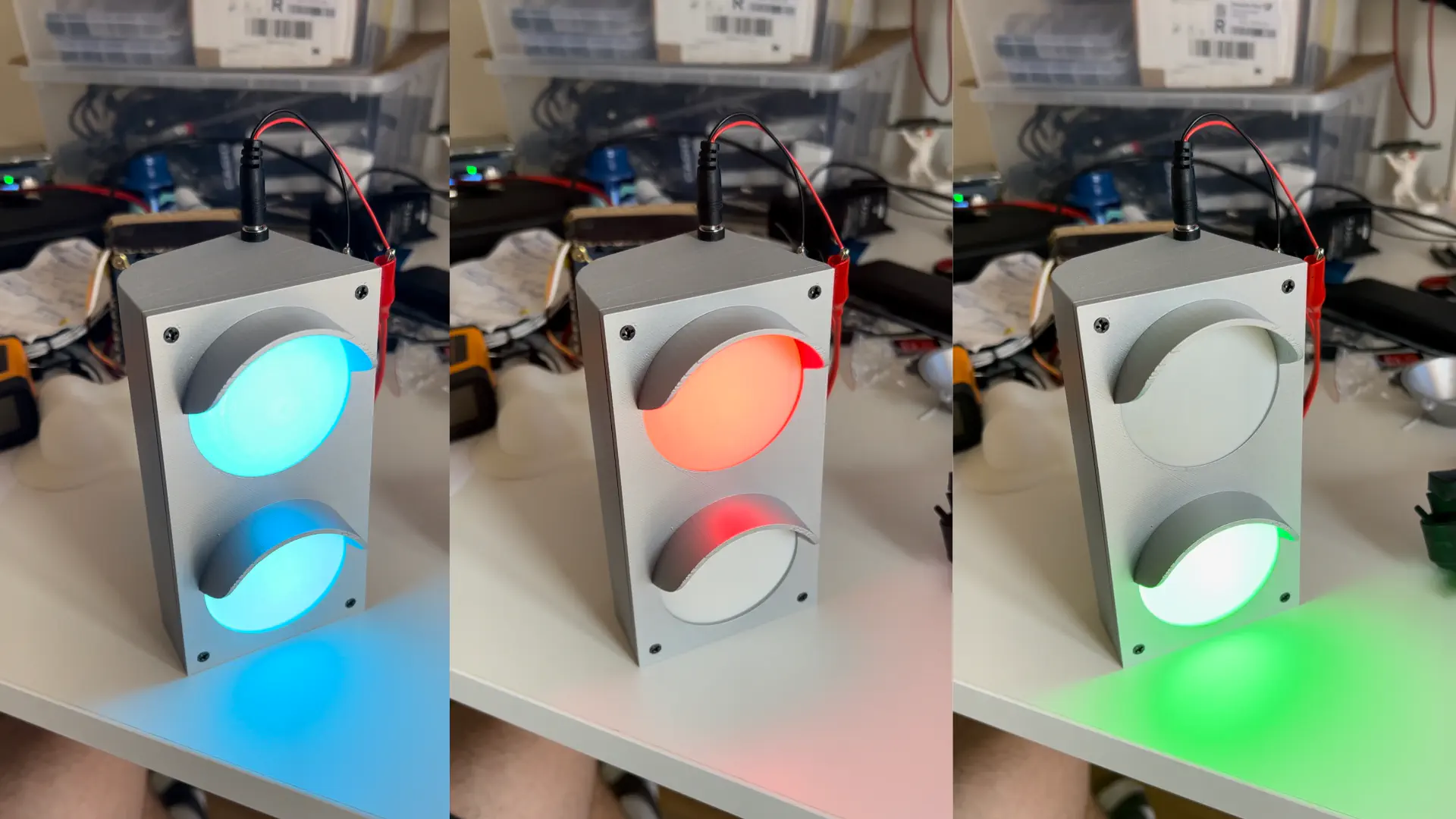
After soldering everything together and applying power, the LEDs lit up and I was able to update the device over WiFi successfully. I wrote some more code to allow switching the lights to green for a few seconds by sending a GET request to the device and added smooth transitions to the color changes.
Result
Finally, I spray painted and assembled the 3D-printed parts, added the electronics and got to enjoy the result.
Links
Comments
This blog does not currently have a comment function. You can send me an email to [email protected] instead and I will add it here.