Introduction bla bla bla…
tuya-convert didn’t work bla bla bla …
Issue 269 on GitHub.
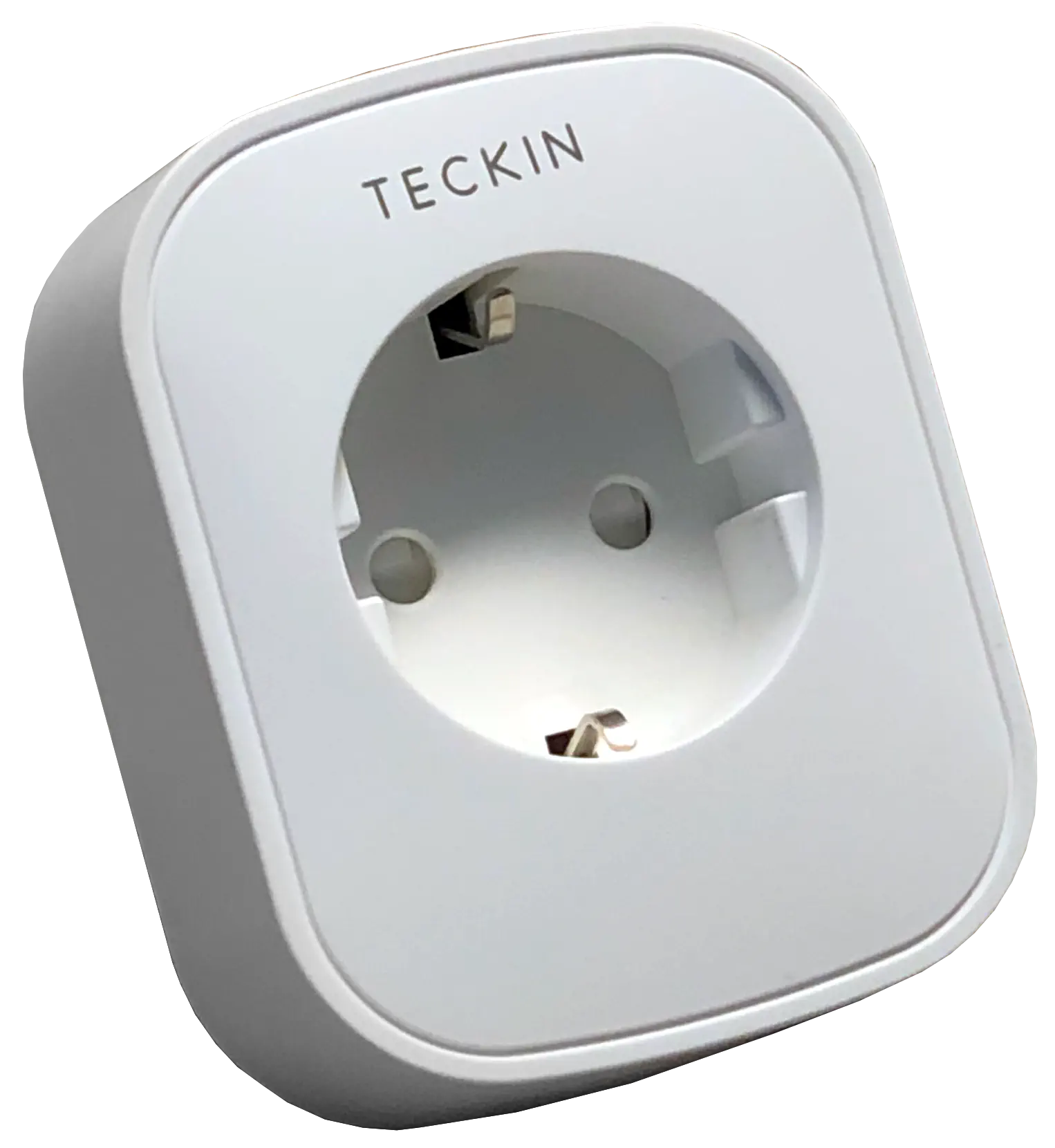
1. Opening the plug
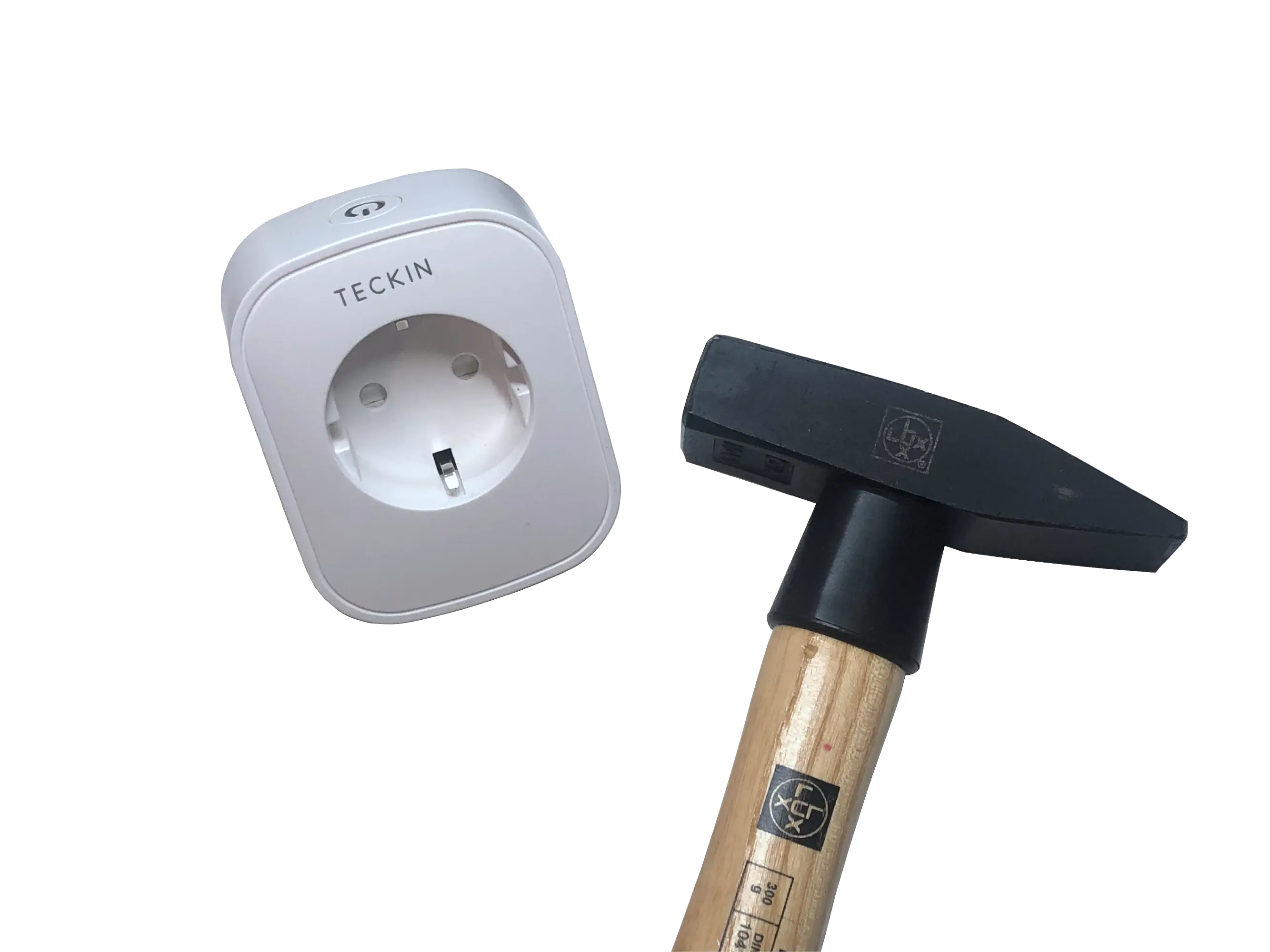
Opening the smart plug depends of the model you have. In my case the plug did not have any external screws, so I went with the advice in this comment and tried hitting it with a hammer. A rubber hammer probably works the best, but in my case wrapping the plug in a towel and hitting it with a regular hammer worked and didn’t leave any big marks either.
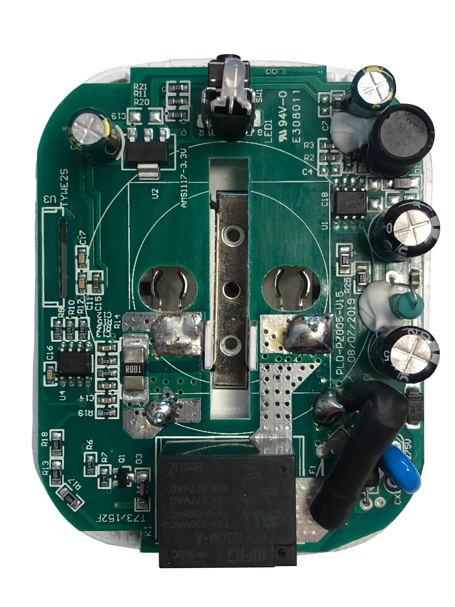
2. Inspecting the wifi module
In this case it turned out, that even though the silkscreen still said TYWE2S, the module did not look like one and did not even seem to have an ESP8266 chip on it. After some research I found, that the TYWE2S module that was originally used in this product, had been replaced by a WR2 module at some point during its production. According to the tuya docs the WR2 module is RTL8710BN based, not ESP8266 based like the TYWE2S, so flashing Tasmota onto it is currently impossible. As only ESP8266 based modules are supported (and no RTL8710BN support is planned) our best bet is to replace the module with a compatible ESP8266 based module.
The module I used and will talk about in this guide is the ESP-12F. It is small, has more than enough GPIO pins and costs only about $1 on AliExpress.
3. Removing the useless chip
Now that we know the old chip is useless to us, we can start by first removing it from the PCB.
Removing the old chip is actually quite tedious, because you have to heat all 11 solder pads at the same time, if you want to pull it out. I can’t really give any advice on this part, other than don’t be too gentle. I ended up breaking a solder pad on the first attempt, but that’s not that much of a problem, as there’s other solder points you can use later.
4. Preparing the ESP8266
As the ESP-12F module is a pretty bare-bones module, you’ll have to add a few resistors before it will even boot. Here’s a super short summary of what pin states are needed for booting the ESP.
HIGH meaning connected to VCC though a resistor and LOW meaning connected to GND through a resistor.
The value of the resistor should be around 10K Ohm, but the exact value is not important. (I used 4.7K Ohm resistors).
Pin states required for booting
| EN (CH_PD): | HIGH |
|---|---|
| RST: | HIGH |
| GPIO02: | HIGH |
| GPIO15: | LOW |
ESP8266 Boot modes
| Mode | GPIO0 |
|---|---|
| Boot | HIGH |
| Flash | LOW |
While all of the connections should be made though resistors, I found that the resistors for pulling EN and RST HIGH, are not neccesary, so I connected them straight to VCC.
For the other pins you simply solder a resistor between GPIO0–VCC, GPIO2–VCC and GPIO15–GND.
ESP-12F ESP-12F
EN ------------------- VCC
RST ------------------ VCC
GPIO0 ---[resistor]--- VCC
GPIO2 ---[resistor]--- VCC
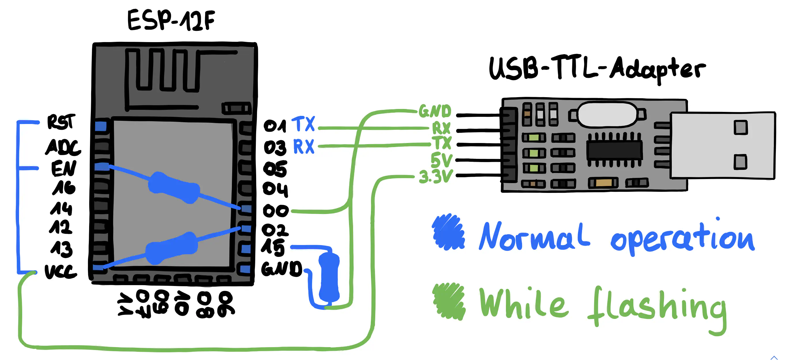
GPIO15 --[resistor]--- GNDIn order to flash the ESP you’ll now have to temporarily solder the wires of an USB-TTL-Adapter to the ESP. The wiring should be as follows:
ESP-12F            USB-TTL
RX -------------------- TX
TX -------------------- RX
VCC ----------------- 3.3V
GND ------------------ GND
GPIO0 ---------------- GND
5. Flashing the ESP8266
After adding the neccesary resistors and connecting the USB-TTL-Adapter to the ESP, the next step is to flash the ESP with the Tasmota firmware. The steps of this are well described in this Getting Started guide in the Tasmota docs, so I’ll keep it short.
After installing esptool.py and downloading tasmota.bin from here, we can simply run:
esptool.py -p /dev/ttyUSB0 write_flash 0x00000 tasmota.bin
The output of it should look something like this:
esptool.py v3.0
Serial port /dev/ttyUSB0
Connecting....
Detecting chip type... ESP8266
Chip is ESP8266EX
Features: WiFi
Crystal is 26MHz
MAC: e8:db:84:9b:ca:9b
Uploading stub...
Running stub...
Stub running...
Configuring flash size...
Compressed 622112 bytes to 443481...
Wrote 622112 bytes (443481 compressed) at 0x00000000 in 39.1 seconds (effective 127.3 kbit/s)...
Hash of data verified.

Leaving...
Hard resetting via RTS pin...
After flashing the ESP, it should create a Wi-Fi called tasmota_XXXXXX-####. Connect to that network and navigate to http://192.168.4.1 to setup the ESP’s Wi-Fi connection. Take note of the IP shown after setting up the WiFi, as we’ll need it step 7.
6. Wiring it up
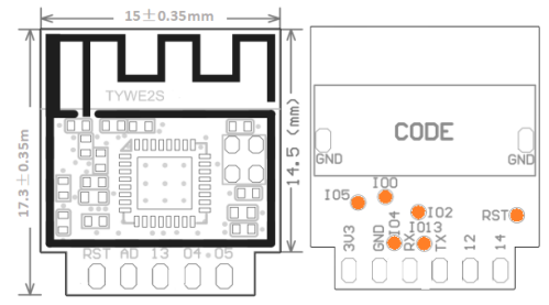
Before soldering the wires, we should probably first figure out which points to solder to. In my case this was actually quite easy. Looking at the Teckin SP22 Tasmota Template and a schematic of the TYWE2S, that the template is assuming, one can simply read off the function and position of each pin.
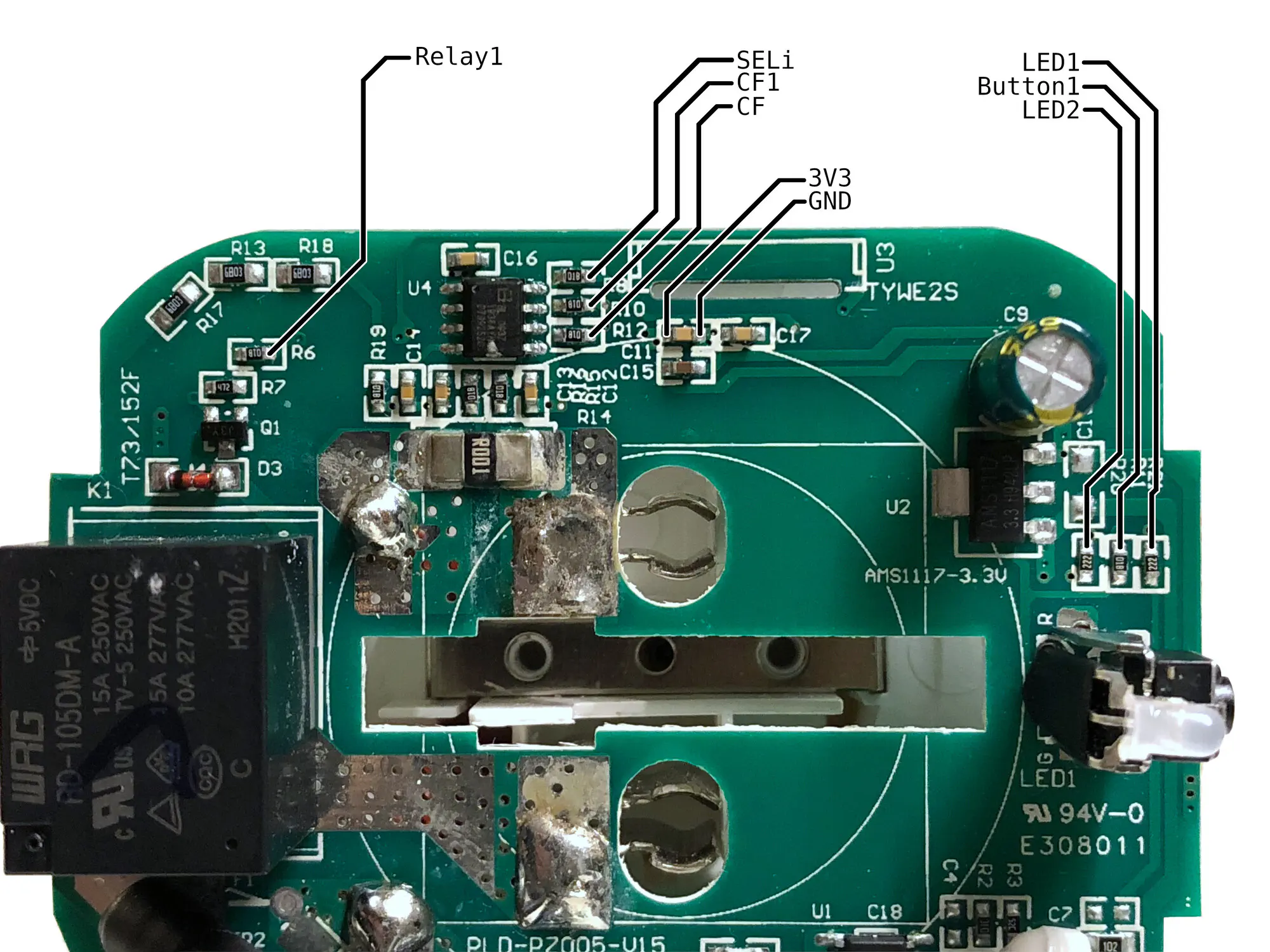
While you can then start soldering to these pins directly, I decided to look for points I could more easily solder to. I found all of the relevant points on the front of the PCB and labeled them in the image below.
In case you want to use the original solder pads, here are the labeled connections:
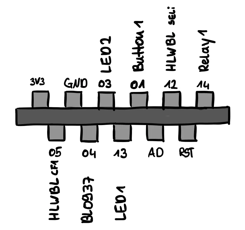
Which connections you connect to which GPIO pin is up to you, but keep in mind that some pins may behave in unexpected ways. Below is a summary, based on the table here.
| GPIO | Input | Output | Notes |
| GPIO16 | OK | OK | HIGH at boot |
| GPIO0 | pulled up | OK | Boot fails if pulled LOW |
| GPIO2 | pulled up | OK | HIGH at boot Boot fails if pulled LOW |
| GPIO15 | pulled to GND | OK | Boot fails if pulled HIGH |
| GPIO3 | OK | RX pin | HIGH at boot |
| GPIO1 | TX pin | OK | HIGH at boot Boot fails if pulled LOW |
Especially for the Relay1 connection I would choose a pin that is not pulled HIGH at boot, as that would close the relay every time the ESP restarts. All other pins can be used normally.
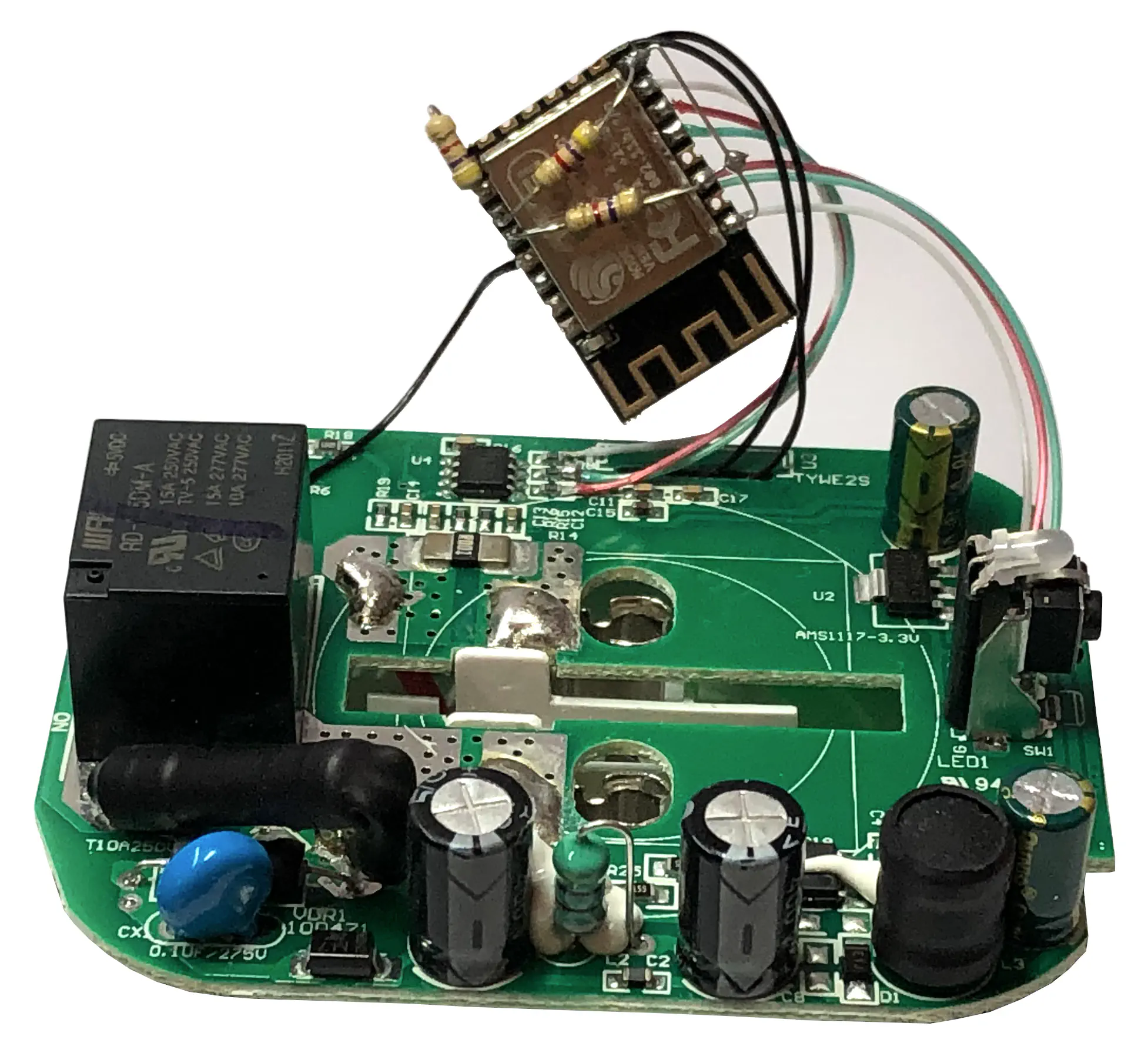
I ended up wiring it as shown in the diagram below:
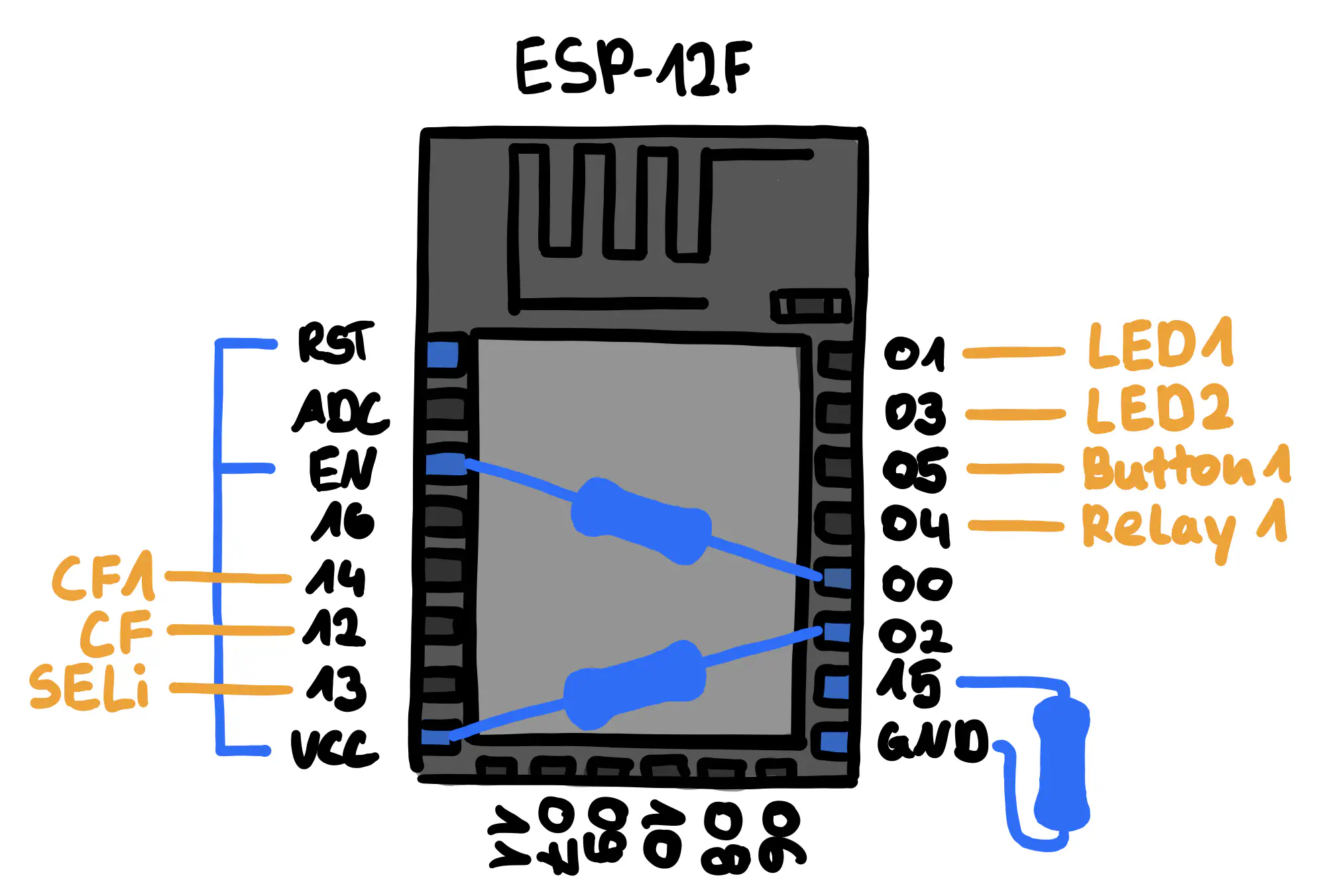
This is what it looks like after wiring up all of the connections:
7. Configuring Tasmota
In case you do test it, plug it into a powered off power strip and make sure nothing is connected or touching it when you turn it on. Turn off the power strip before attempting to unplug the smart plug.
Configuring Tasmota should be quite simple of you remember which wire you soldered where.
8. Done
After checking that the Tasmota configuration works we can simply re-assemble the plug and we are done.
Sources and Resources:
\[tasmota.github.io\] Tasmota: Getting Started guide
\[randomnerdtutorials.com\] Notes on ESP8266 GPIO pins
\[templates.blakadder.com\] Tasmota Template: Teckin SP22
\[developer.tuya.com\] Datasheet: TYWE2S module
\[developer.tuya.com\] Datasheet: WR2 module
Comments
This blog does not currently have a comment function. You can send me an email to [email protected] instead and I will add it here.