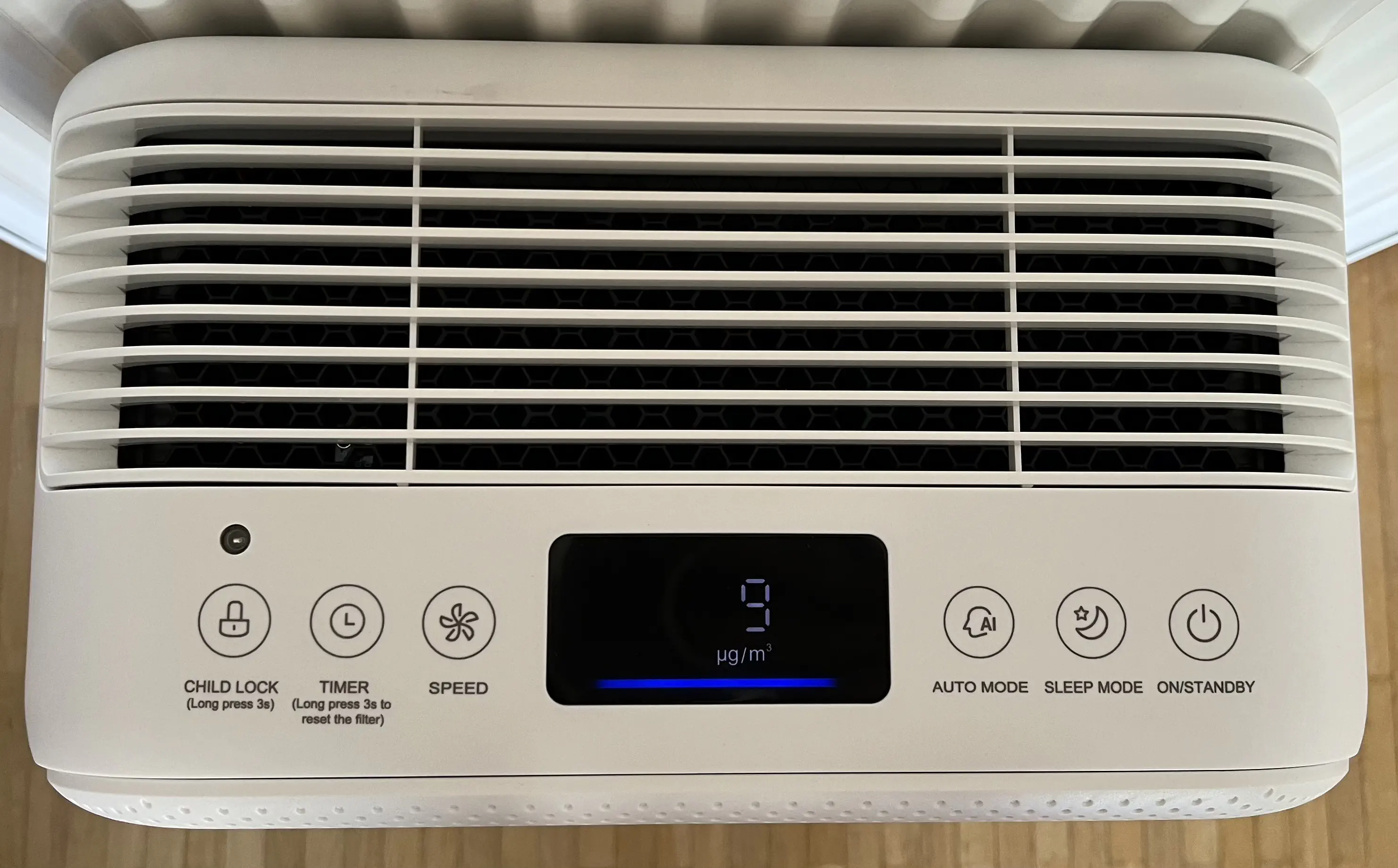
I recently bought an air filter, because pollen season was approaching and it was heavily discounted on Amazon. When it arrived I was pleasantly surprised by its high build quality and the fact that it has a build-in particle sensor to dynamically adjust its fan speed.
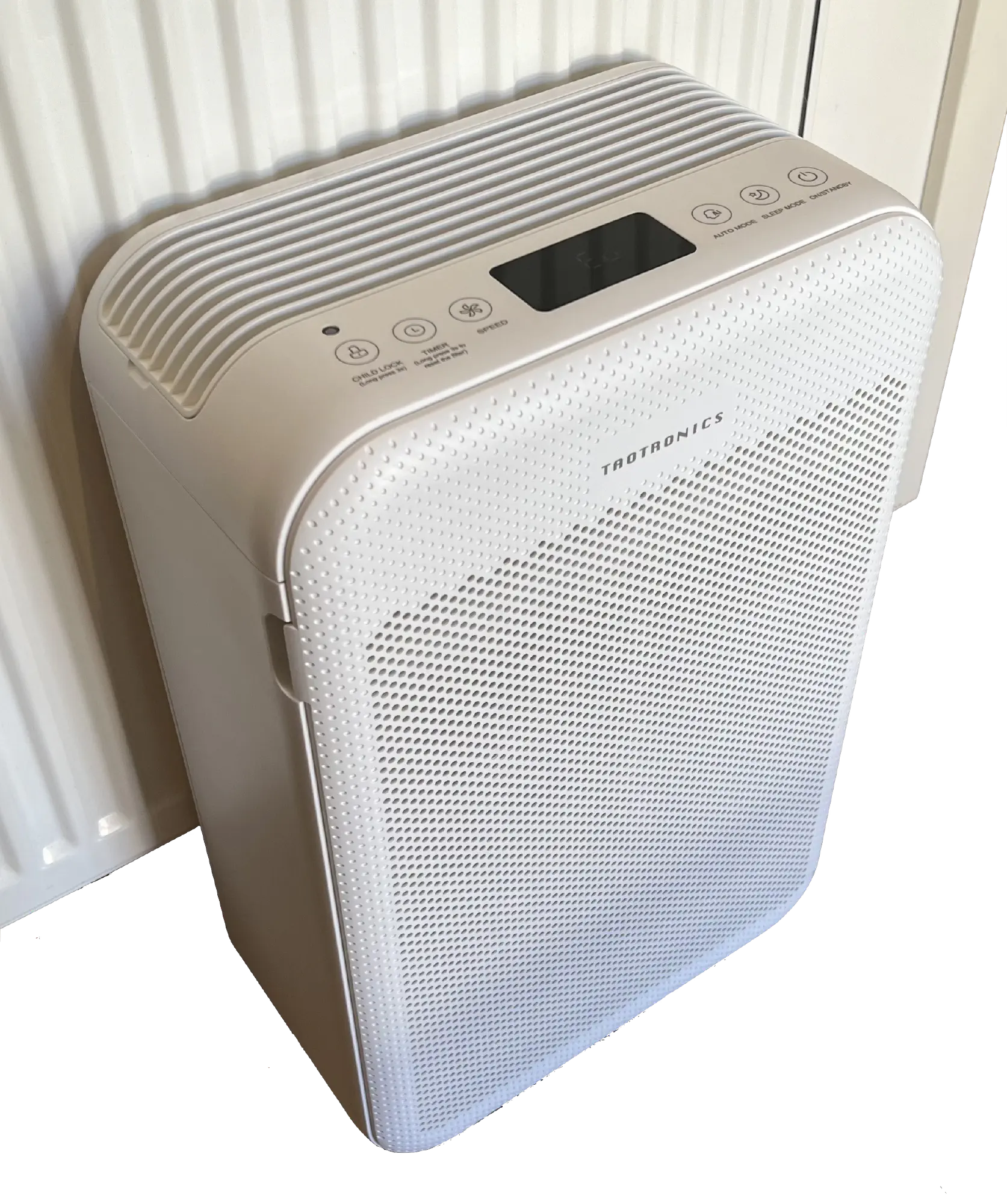
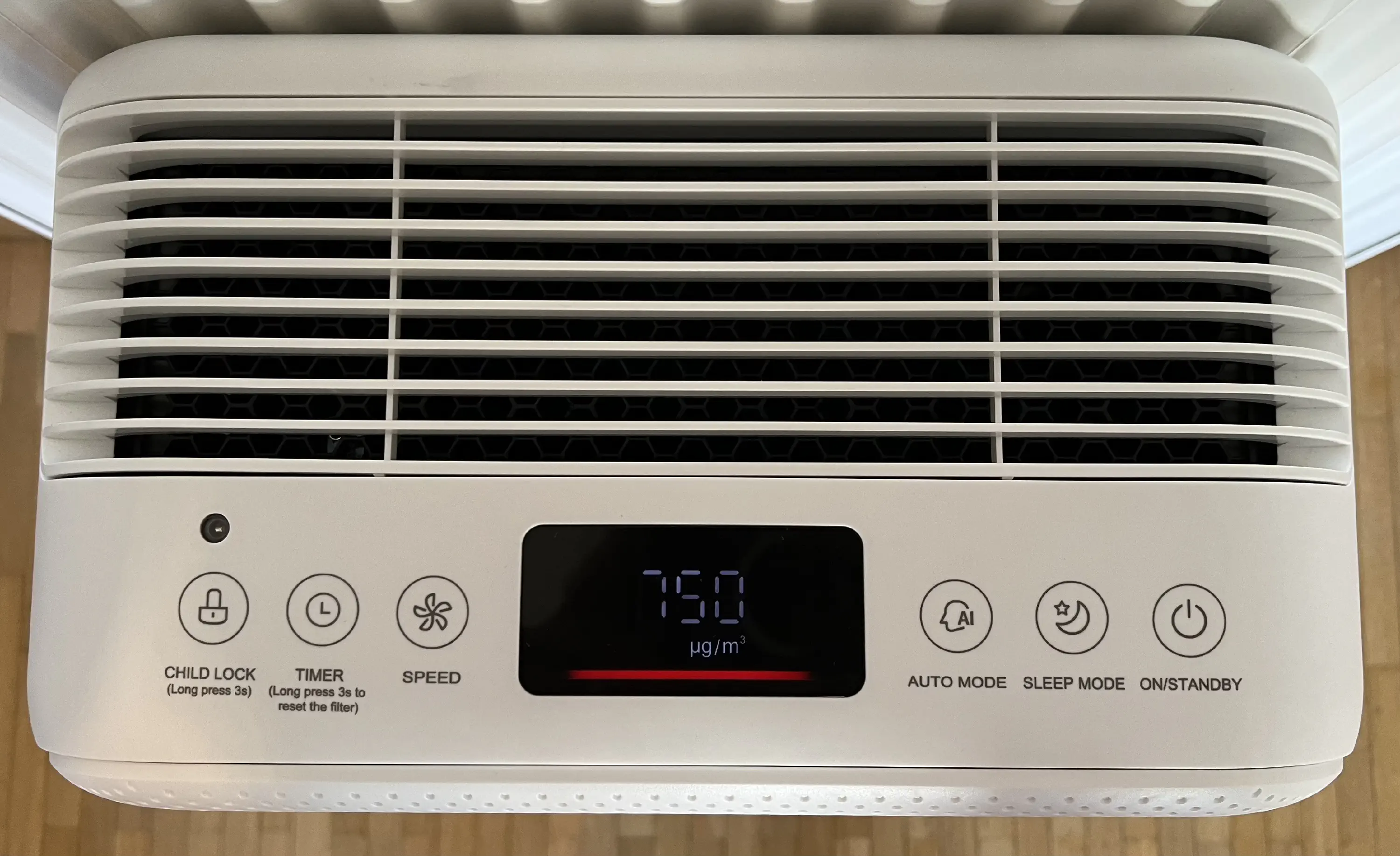
When I started using it, I always enjoyed checking the current particle count every time I walked past it. Sometimes the value was high and I tried to figure out what had caused it. Usually these were things such as vacuuming or cooking, but sometimes I could not explain why the value had gone up. After wondering about these events and about how the particle count in the air behaved while I was gone or asleep, I decided that it would be a fun project to build a system that would log these values automatically, so they could be plotted and analysed on demand.
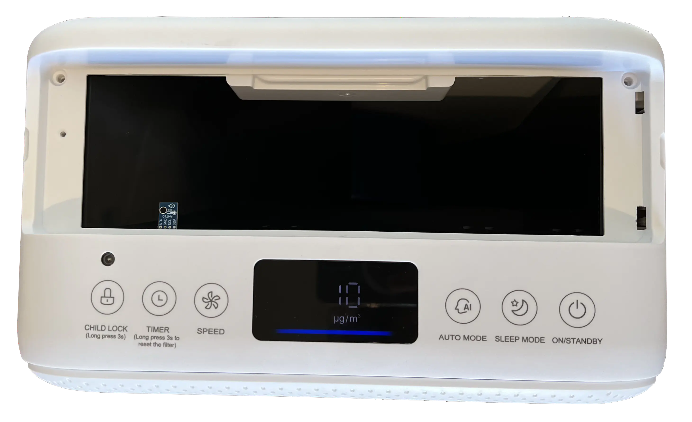
Opening the device
Opening the device proved to be quite difficult, owing to the fact that it seems to be held together by hundreds of screws and clips. (This is probably why it feels so sturdy and high quality.) Once I found the right places to apply force to, I was able to open it without any permanent damages. I have attached a photo of the most important clips for anyone interested in replicating this.
PHOTOS
The PCB
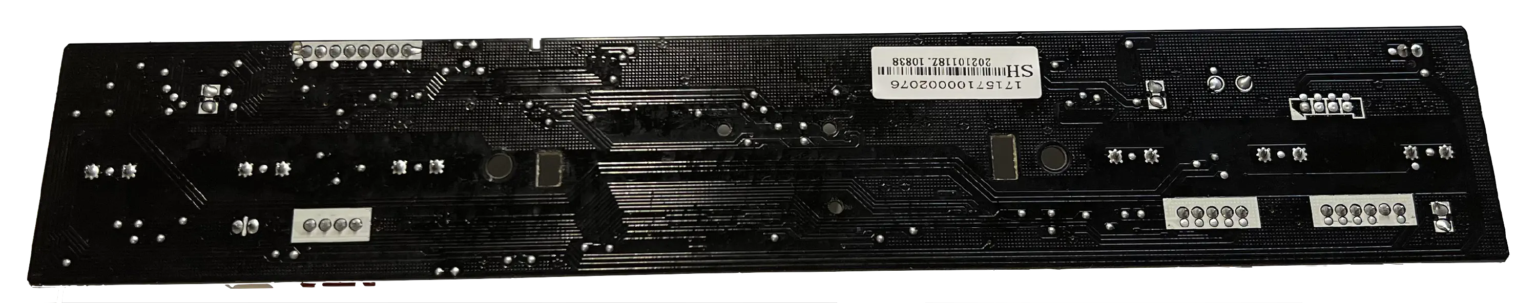
After taking prying off the plastic panel at the top I got a first proper look at the PCB that takes the user and sensor input and controls the fan speed.
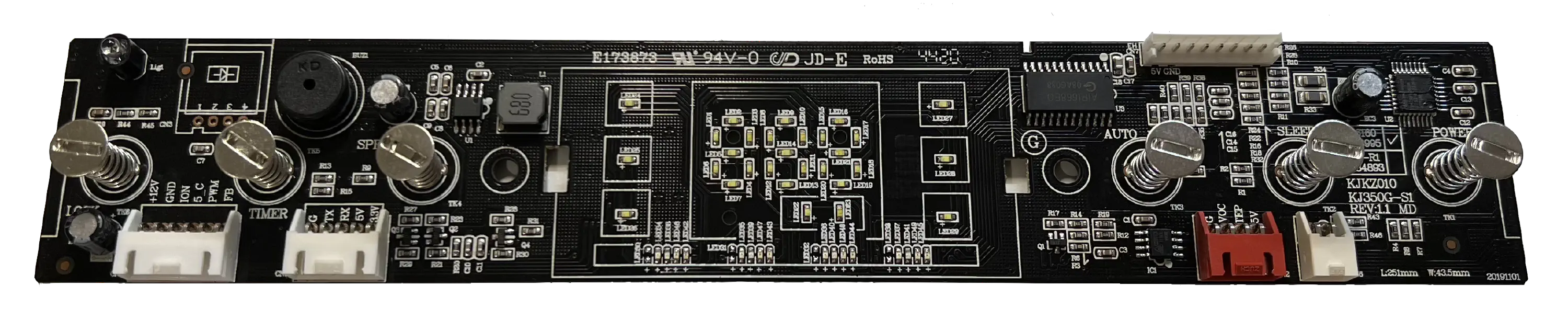
The connectors are from left to right:
- power input & fan motor control
- connection to particle sensor
- unknown (connector for some type of VOC sensor?)
- front panel open reed switch
The metal discs on springs are part of the the touch controls of the air filter. They appear to be capacitive touch buttons that work through the housing.
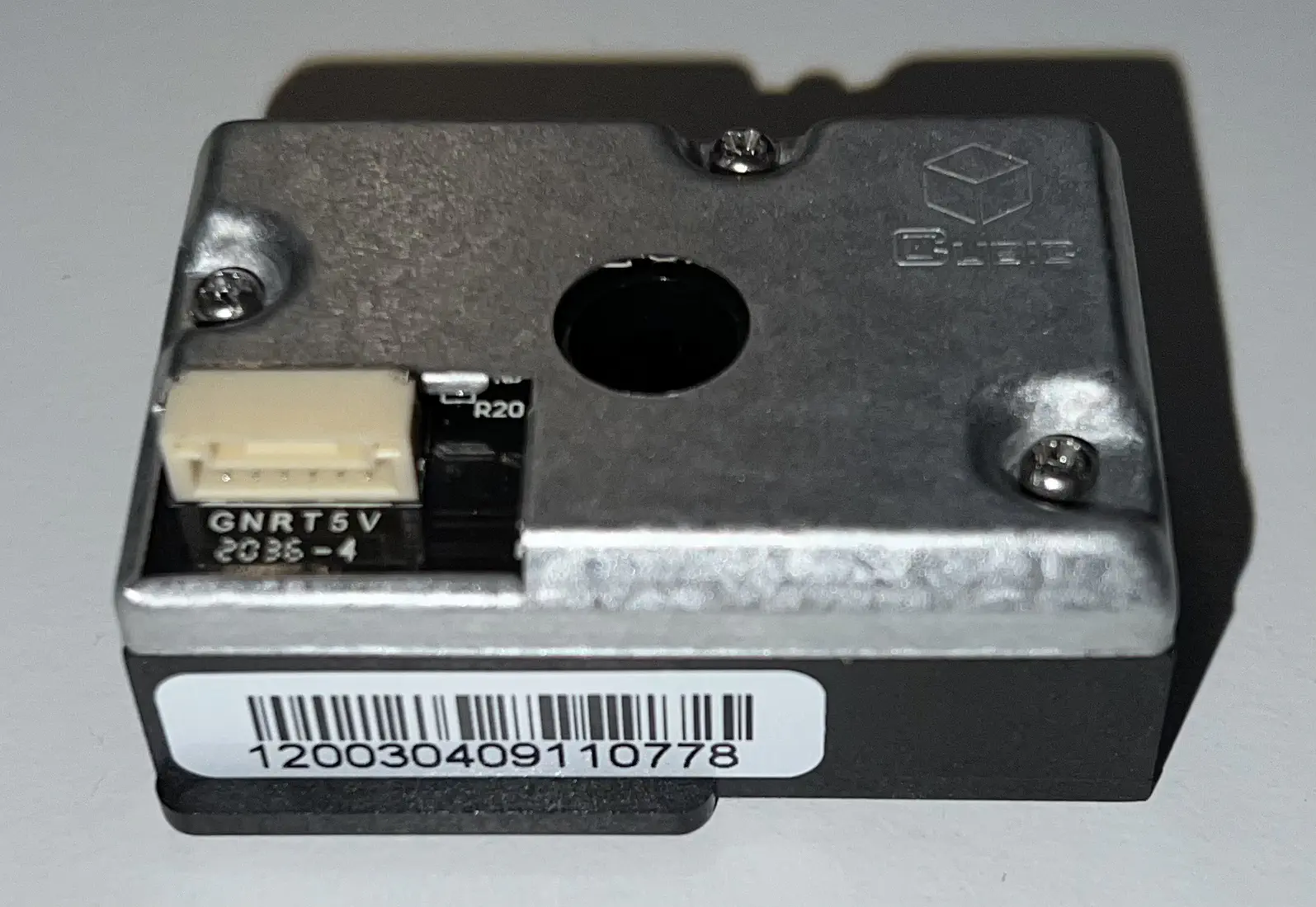
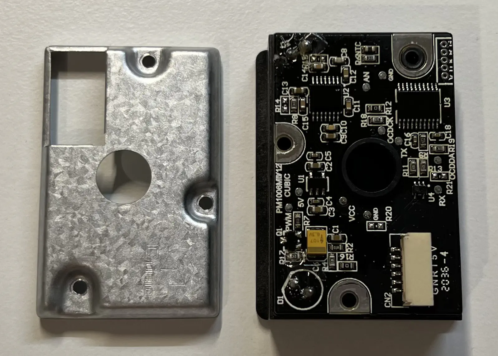
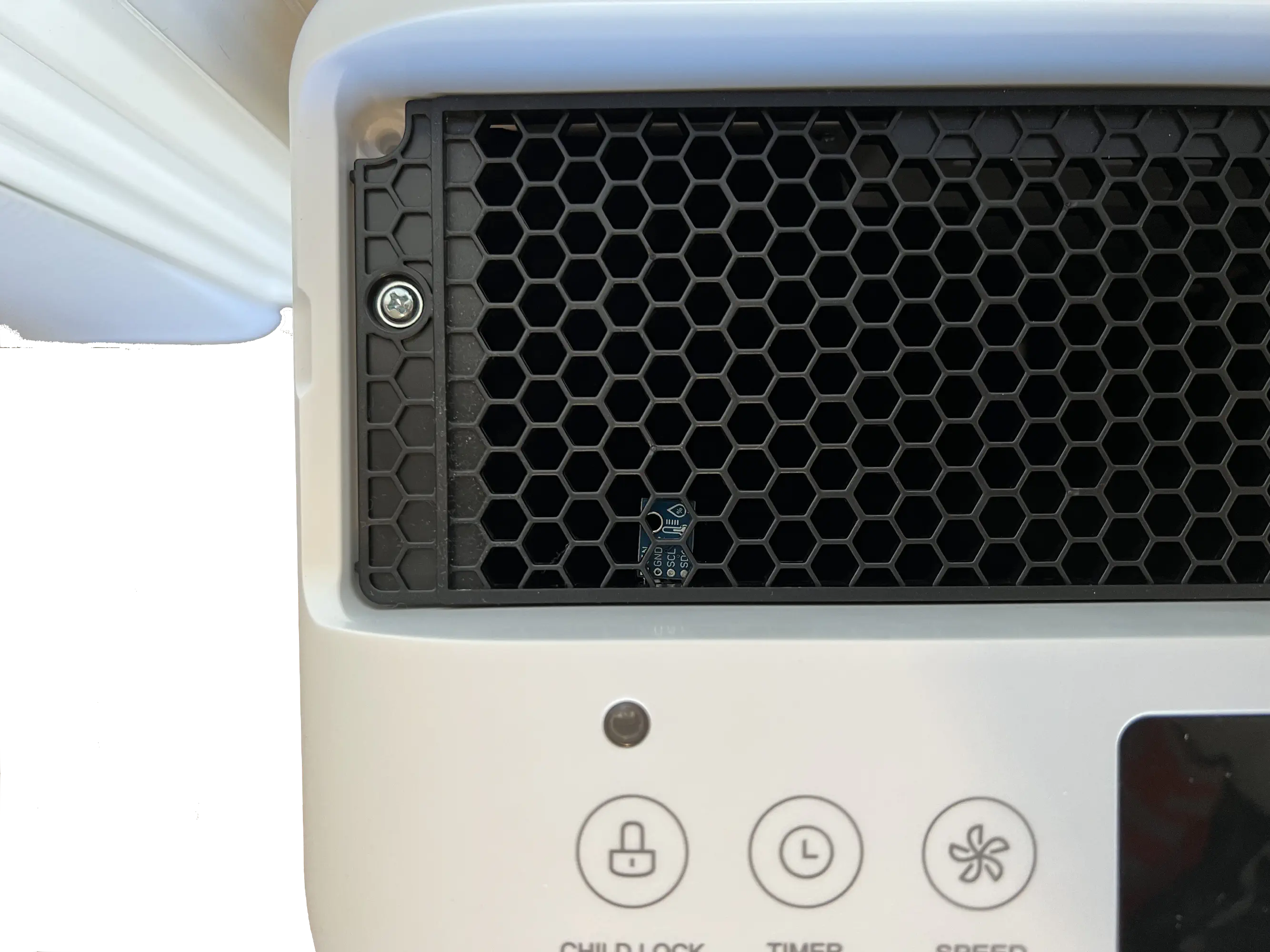
The particle sensor
The second part I immediately looked for is of course the particle sensor. I found it in the front of the device, where it used the airflow of the main fan to ingest air. According to the label this appears to be a PM1006M sensor by Cubic. While I could not find any information or datasheets for the PM1006M, I found that a very similar sensor, the PM1006K, is well documented by the smart home community, because it is included in an easily hackable IKEA air quality monitor (IKEA VINDRIKTNING).
Reading data
I captured some communication between the air filter and the sensor, which fortunately seemed to use the same protocol as described in the PM1006K datasheet. Only at the beginning were there some undocumented packages, that seemed to contain information about the sensor. Because of this, I assume that the pm1006 library by bertrik would work for this sensor too. I did not test it, because I ended up writing my own code to add the functionality described below.
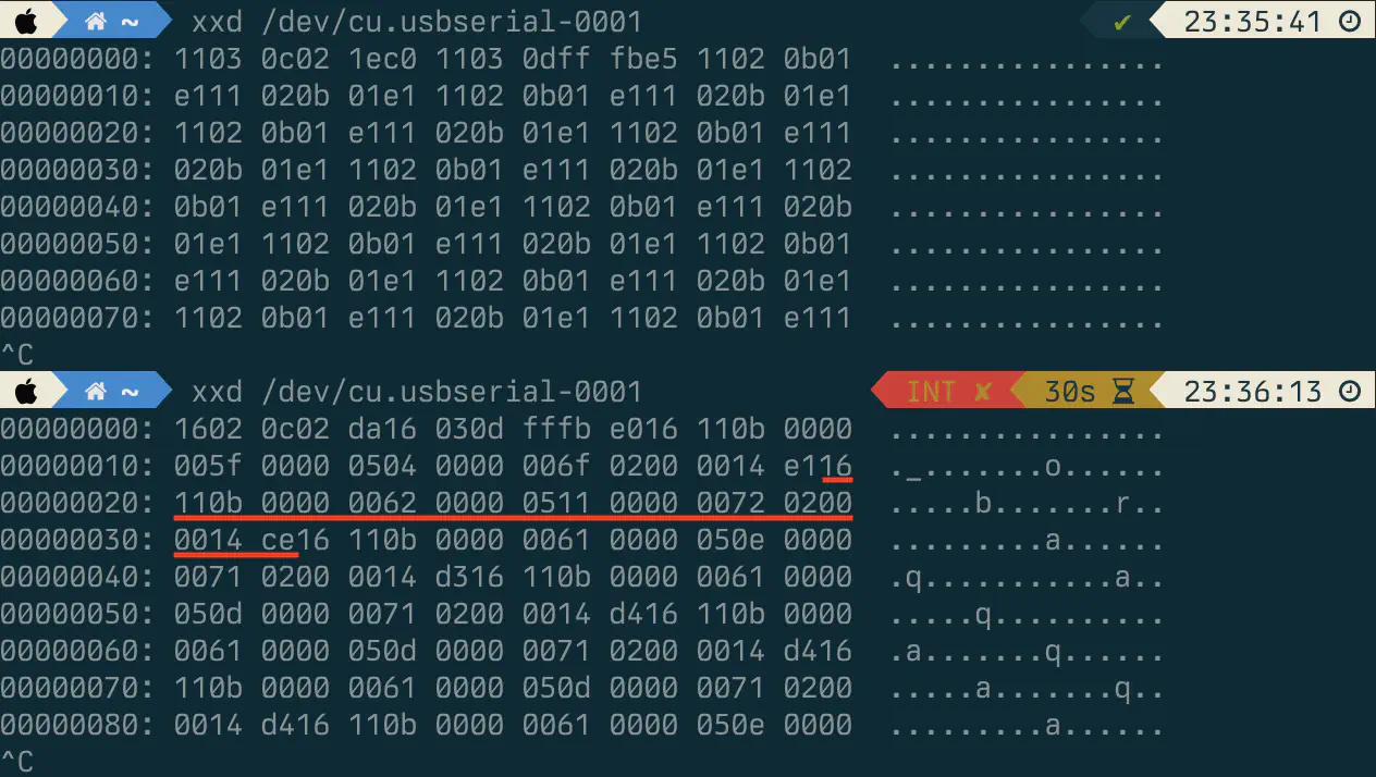
The output looks much like the one described in the manufacturers datasheet, where it is described like this.
Response: 16 11 0B DF1-DF4 DF5-DF8 DF9-DF12 DF13-DF16[CS]
Note: PM2.5(μg/m3)= DF3*256+DF4
Controlling the fan speed
Emulating touch?
One feature that I really wanted to add, now that I had already taken apart the filter and was about to put in a wifi-enabled chip anyways, was to have the ability to control the fan speed of the air filter. I first looked into how I could interact with the “touch” controls using the ESP8266, but upon further research found out, that emulating presses on these capacitive touch buttons is much harder than expected. The only method that I could find would involve adding a relay with a tinfoil attached to one side, in order to allow increasing the capacitance on demand.
After getting frustrated from researching ways to emulate button presses, I suddenly had a great idea. If I was to read the PM25 values from the sensor, I should easily be able to create fake sensor output too. This way I could just set the air filter to auto mode and control the fan speed by sending manipulated values to the air filters MCU. But for this I would have to really understand the communication protocol and could not rely on an preexisting library.
Man-in-the-Middle
Having seen that the serial protocol is very similar I first had a look the the code of the pm1006 library by bertrik . In contrast to the documentation by the manufacturer, the library actually made use of the checksum at the end of each packet, which is important, as the air filter would not accept packets without the correct checksum. From the library I reconstructed this more detailed description of the packets.
      16 11 0b 00000061 0000050d 00000071 02000014 d4
     /   |   \    '--------'--------'--------'     |
HEADER LENGTH COMMAND     DATA[LENGTH]          CHECKSUM
All the data plus the checksum should add up to zero, so the checksum can be calculated by adding up all bytes of the message and XOR’ing it with 0xFF and incrementing it by one. I found this online checksum calculator that really helped test and debug my checksumming code. In my code I used the following snippet to calculate the checksum:
checksum = (checksum^0xFF);
checksum++;
outgoing_byte = checksum;
After understanding the protocol, writing the code was as simple as passing through all data except for the bytes containing the particle count value and the checksum at the end.
Summary of the code handeling the sensor data
- The code waits for a start byte of 0x16 to determine the start of a packet and then checks if the next two bytes are the contain the expected values for packet length and command (0x11 and 0x0B respectively).
- Of the data that follows only the 3rd and 4th byte are relevant, the rest is discarded. As per the documentation the 3rd and 4th byte are combined like
value = BYTE[3] * 256 + BYTE[4]to get the sensor value. - At this point the fake value that is to be sent to the air filters MCU gets converted into individual bytes and sent out. (
BYTE[3] = value / 256; BYTE[4] = value % 256) - The next bytes are discarded, until the last byte is reached. This byte is the checksum, so it will have to be manipulated too in order to send out fake values. For this the bytes of the outgoing data are added up in a counter when they get sent out and this counter can now be subtracted from 0xFF to calculate the new checksum.
- After sending out this final byte the cycle repeats.
Wiring
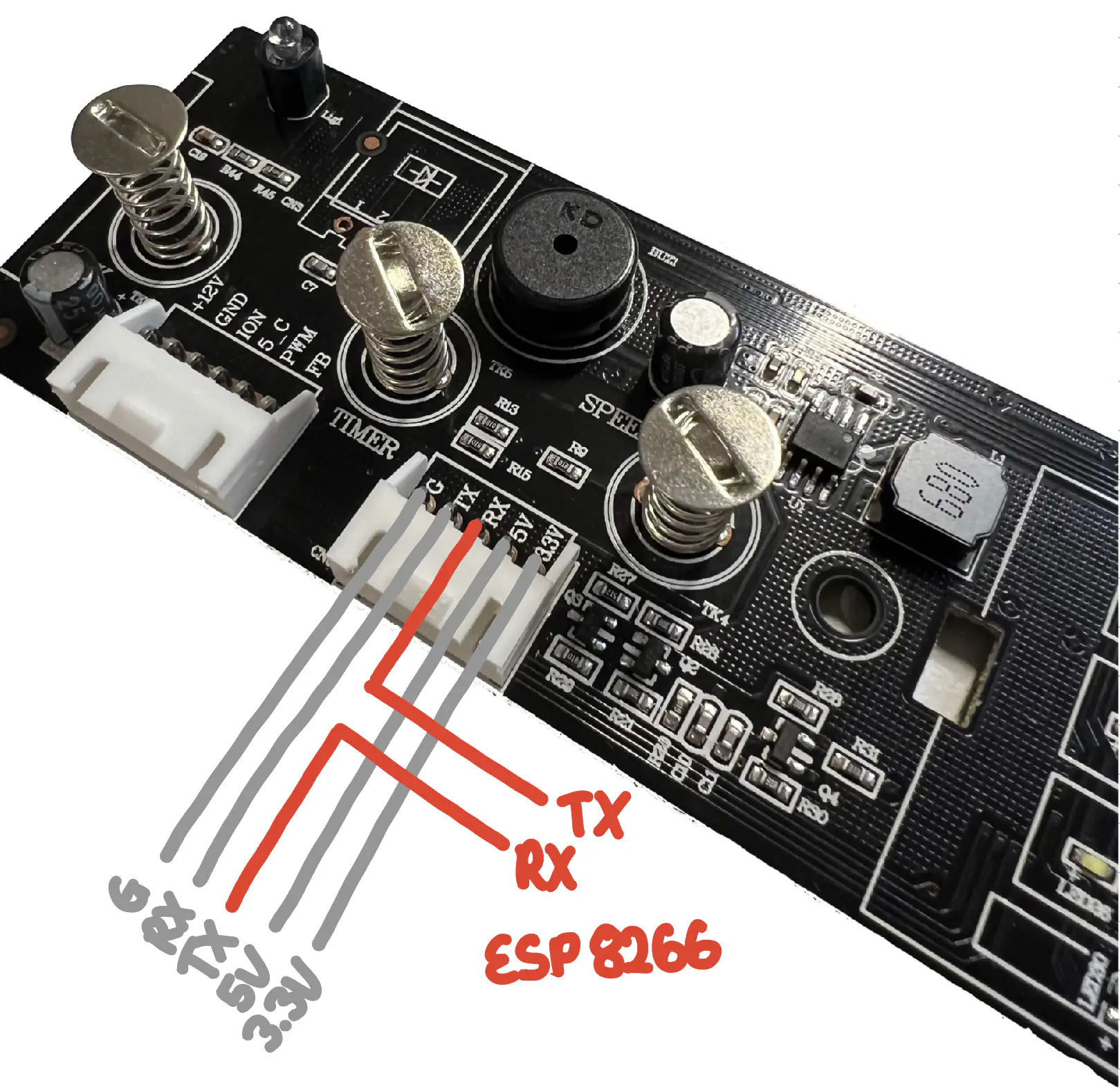
Wiring it up was straight-forward. I ended up wiring it up like this:
Filter  TX -> RX Sensor
Sensor  TX -> RX ESP8266
ESP8266 TX -> RX Filter
Go get power, I used an ADS1117 LDO to convert 5v that I found on the air filters PCB to 3.3v for the ESP8266. The line marked 3.3V to the particle sensor seemed to be varyiing around 4.5V most of the time and therefore unsuited to be used as the power source for the ESP8266.
The overall code
Main loop
- Read data from serial
- Intercept and modify bytes representing PM data and checksum
- Output data to serial
Interval (default 10s)
- Read AHT10
- Publish particle, temperature and humidity data on MQTT
On MQTT message received
- Set value to output
Success
Adding a temperature sensor
Comments
This blog does not currently have a comment function. You can send me an email to [email protected] instead and I will add it here.